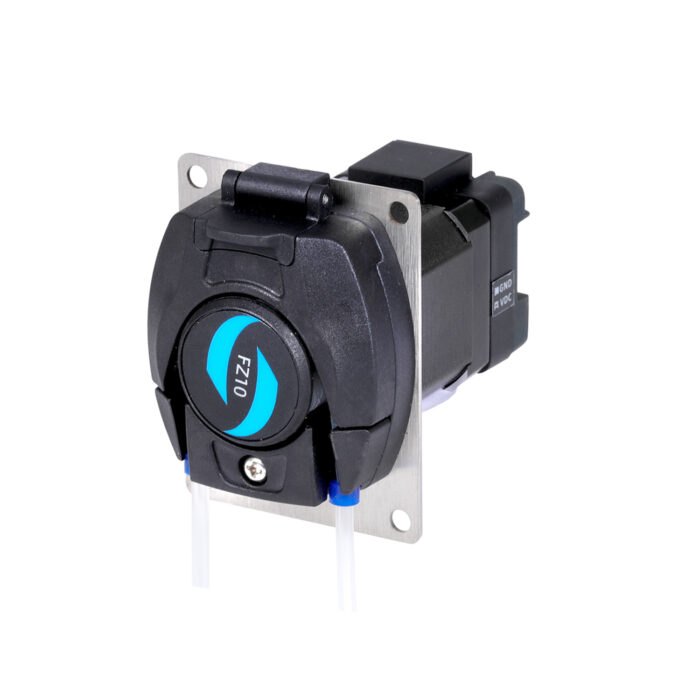
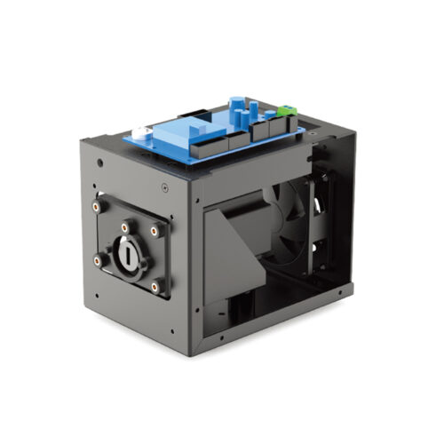
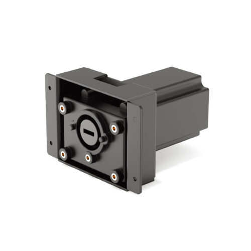
Introduction
•With running status output function;
•It can adapt to various tubes
•Small and compact with an attractive and aesthetically pleasing design
•Quiet operation;
•Ideal for continuous operation at low speeds.
Parameters
Motor Types: 42 stepper motor
Power Supply Voltage: DC12V-24V
Power: <20W
Speed Range: ≤100rpm
Control Mode: RS485(Modbus RTU)
Baud: 9600
Check Bit: Parity check/No parity check (configurable via DIP switch)
Data Bit: 8
Stop Bit: 1
Suitable Tubes: Silicone tube
Start-Stop Method: External Pulse Signal Control (DC 12-24V) / RS485 Communication
Direction Switch Method: External Pulse Signal Control (DC 12-24V) / RS485 Communication
Running Direction: Clockwise/Counterclockwise rotation
Pump Head Compression Block/Base Material: PPS
Material of the Roller Shaft: SS304
Material of the Mounting Plate: SS304
Noise: ≤60dB (testing environment noise ≤40dB, horizontal distance between test product and noise meter is 1 meter)
Driver Weight: 521g
Dimensions: (L*W*H) (95*60*80mm)
Working Environment: Temperature 0- 40°C, , Relative humidity< 85% RH
Storage Environment: In a clean and well-ventilated environment with ambient temperatures ranging from -40 to +50°C, and relative humidity not exceeding 95%, the air must not contain corrosive, flammable gases, oil mist, or dust.
Tube Model and Flow Reference Table
| Tube Material | Tube Size(ID* wall thickness) | Flow Rate(mL/min) | |||||
| 1rpm | 20rpm | 40rpm | 60rpm | 80rpm | 100rpm | ||
| Silicone | 0.5*092 | 0.015 | 0.3 | 0.6 | 0.9 | 1.2 | 1.5 |
| 1*092 | 0.06 | 1.2 | 2.4 | 3.6 | 4.8 | 6 | |
| 2*092 | 0.2 | 4 | 8 | 12 | 16 | 20 | |
| 2.4*092 | 0.27 | 5.4 | 11 | 16 | 22 | 27 | |
| 3*092 | 0.4 | 8 | 16 | 24 | 32 | 40 | |
•The above flow data were all tested using a Lead Fluid silicone tube to pump pure water under laboratory conditions with normal temperature and pressure. This data is for reference only.
•Due to pressure in actual use , temperature, medium characteristics, tube material and other specific factors, the specific situation needs to consult our engineers.
Head Pump Structure
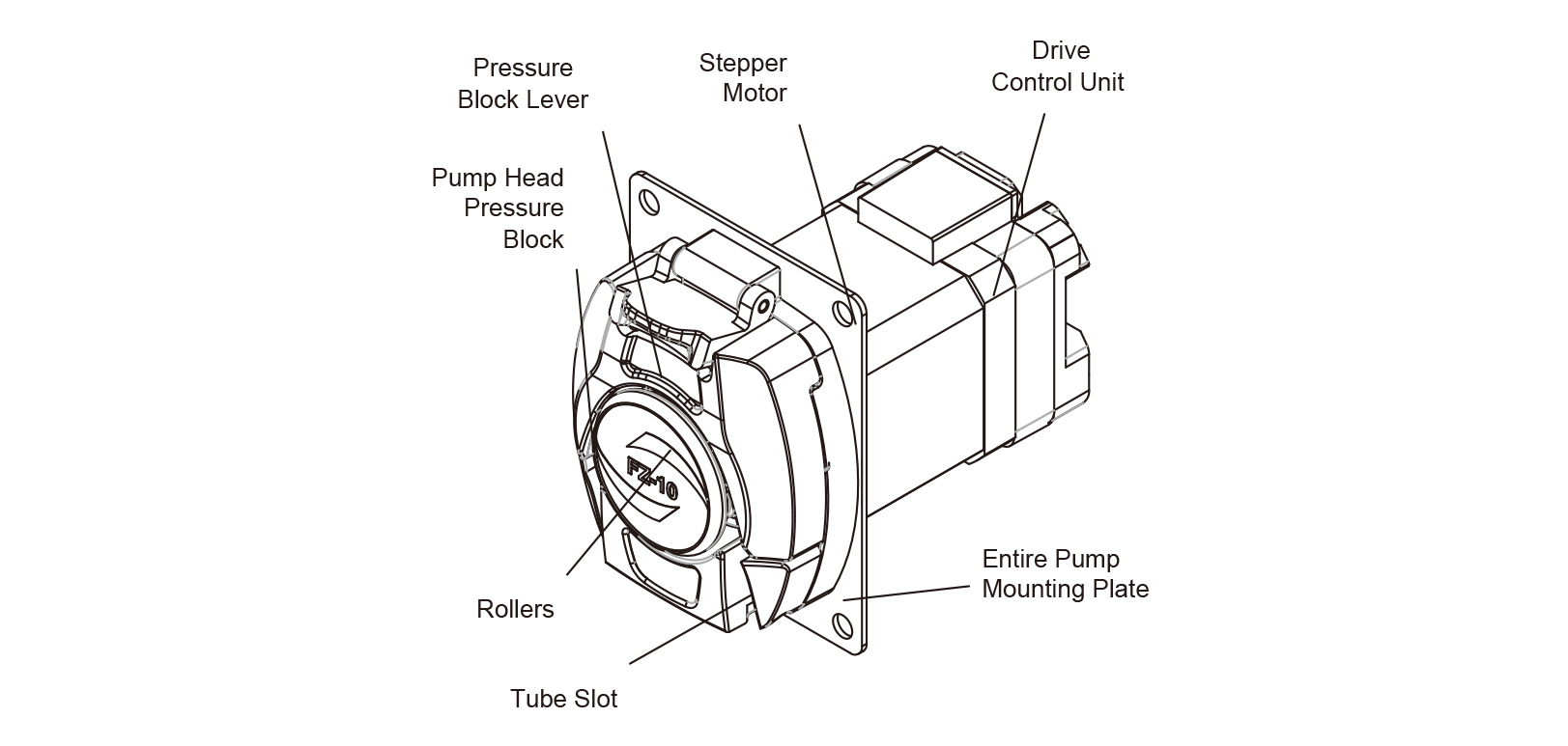
Component name and function:
• The pressure block lever: Pull it upwards, and the pump head pressure block will rise, making it possible to install or remove the tube.
• Pump head pressure block: After installing the tube, push down the pressure block lever to reduce the gap between the pump head pressure block and the roller body, thereby achieving the effect of tightening the tube-line.
• Rollers: This component works together with the pump head pressure block to compress the tube. Additionally, it uses the rotation of the rollers inside the roller body to squeeze the tube, enabling the transfer of fluids.
• Tube slot: The inlet and outlet tubes are fixed in place through the tube slot.
• The stepper motor: The rotation of the stepper motor drives the rotation of the roller.
• The drive control unit: manages the stepper motor’s speed, direction, and operating duration settings.
• The entire pump mounting plate: It attaches to the customer’s equipment using four through holes on the mounting plate.
Figure 1 Products Structure
Tube Installation
• Lift the pressure lever upwards, which will cause the pump head pressure block to rise as well. Position the tube-line that you’ve prepared between the roller and the pump head pressure block, as shown in Figure 2
• The inlet and outlet ends of the tube need to be fitted with clamps, with an internal spacing of 89mm (internal spacing of the clamps). As shown in Figure 3, after positioning the tube properly, press the lever of the pressing block down to secure it.

Figure2 Pump Head Installation Diagram Figure3 Pump Head Installation Diagram
