Introduction
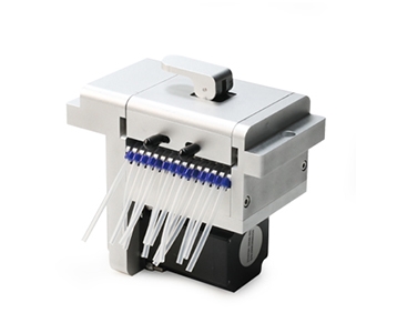
• Suitable for various kinds of pump head.
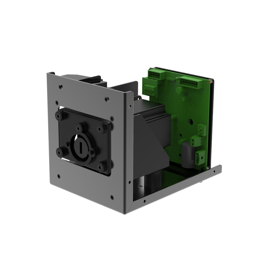
• Small size, compact structure, beautiful appearance.
• Low operating noise.
• Suitable for high-speed continuous operation.
Parameters
Motor Type: 57 stepper motor
Voltage: DC24V-DC36V
Wattage: <50W
Speed Range: ≤150rpm
Adaptable Pump Head: DS10
Rotation Direction: Clockwise / Counterclockwise
Pump Head Bracket Material: ABS-D1200 plastic
Mounting Plate Material: Q235A carbon steel
Pump Head Life: ≥6000h
Noise: ≤60dB (test environment noise ≤40dB, test product and noise meter horizontal distance of 1 meter)
Weight: 2027g (without pump head)
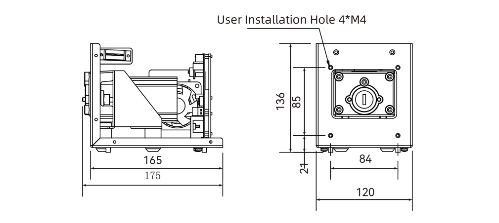
Dimensions: (L×W×H) 175*120*136(mm)
Static Torque: 1.2N·M
Working Environment: Temperature 0- 40°C, relative humidity<80% RH
Storage Environment: Ambient temperature of -40 ~ +50 °C, relative humidity of not more than 95% of the clean and well-ventilated environment, the air shall not contain corrosive, flammable gases, oil mist, dust.
Suitable Tube Model and Flow Rate Reference
Flow Rate Table (Example YZ15, other pump heads refer to the pump head tube flow rate table, unit: mL/min)
| Tube Material | Tube | 1rpm Flow Rate | 30rpm Flow Rate | 100rpm Flow Rate | 150rpm Flow Rate |
| Silicone tube | 13# | 0.05 | 1.50 | 5.00 | 7.50 |
| 14# | 0.20 | 6.00 | 20.00 | 30.00 | |
| 19# | 0.50 | 15.00 | 50.00 | 75.00 | |
| 16# | 0.80 | 24.00 | 80.00 | 120.00 | |
| 25# | 1.90 | 57.00 | 190.00 | 285.00 | |
| 17# | 3.00 | 90.00 | 300.00 | 450.00 | |
| 18# | 4.30 | 128.00 | 427.00 | 645.00 |
Above flow parameters are obtained by using silicone tube to transfer pure water under normal temperature and pressure,in actually using it is effected by specific factors such as pressure, medium etc. Above for reference only.
Product Structure & Usage Method
Product Structure
Component Name and Function
1.Pump Head Bracket: Connects the product and pump head.
2.Mounting Plate: Connects the motor to the pump head bracket and allows the product to be installed on other devices.
3.DB15 External Control Interface: External analog control and RS485 communication control.
4.Power Terminal: Connect DC power supply to power the product (positive and negative poles of the two ports of the green terminal can be mixed).
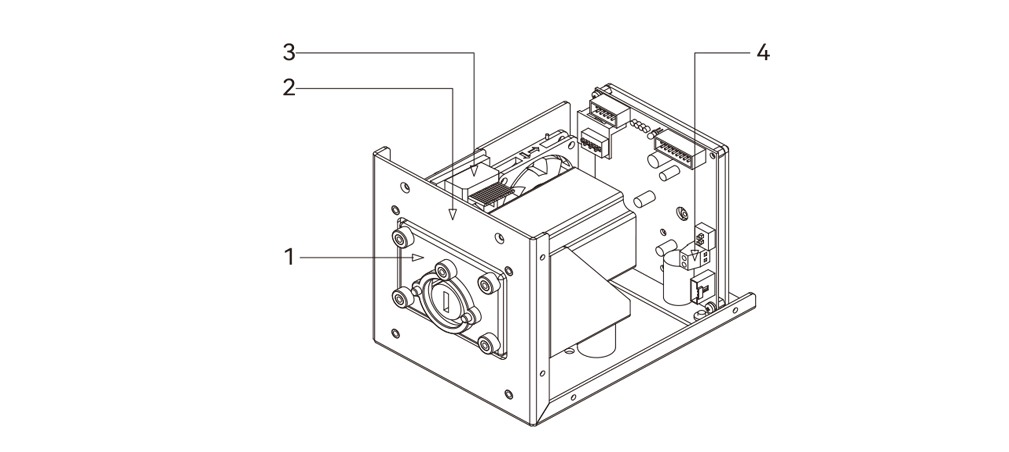
Figure 1 Overall Structure Diagram
Usage Method
Tube Installation
Take 2 screws of the corresponding pump head and connect them through the mounting holes 1 and 2 of the pump head with the threaded holes 1 and 2 of the product pump head bracket (YZ15 pump head example)
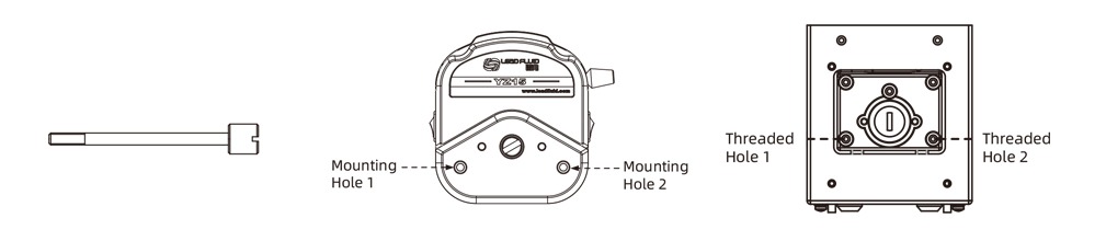
Figure 2 YT25 Screw Diagram Figure 3 YZ15 Mounting Hole Diagram Figure 4 Pump Head Mounting Hole Diagram
Dimension Drawing of Exterior and Opening
Unit: mm
 Statement:The final explanation right of above information belongs to Lead Fluid.