Introduction
•This product series includes three models: B200K1KD15 / B200K2KD15 / B200K3KD15;
•Control mode: analog speed regulation (4-20mA/0-5V/0-10V optional);
•External level signal control start/stop/direction function;
•With running status output function;
•It can adapt to various tubes;
•Small and compact with an attractive and aesthetically pleasing design;
•Low running noise;
•Ideal for continuous operation at low speeds.
Parameters
Motor Types: 42 stepper motor
Power Supply Voltage: DC 12 -24V
Wattage: <20W
Speed Range: ≤200rpm
Control Mode: Analog (4-20mA/0-5V/0-10V)
Suitable Tubes: Silicone tube
Start-Stop Method: External Level Signal Control (DC 12-24V)
Direction Switch Method: External Level Signal Control (DC 12-24V)
Running Direction: Clockwise/Counterclockwise rotation
Material of Pump Head Shell: PVDF
Roller Material: PVDF
Material of the Roller Shaft: SS304
Material of the Mounting Plate:SS304
Noise: ≤60dB (testing environment noise ≤40dB, horizontal distance between test product and noise meter is 1 meter)
Driver Weight: 588g
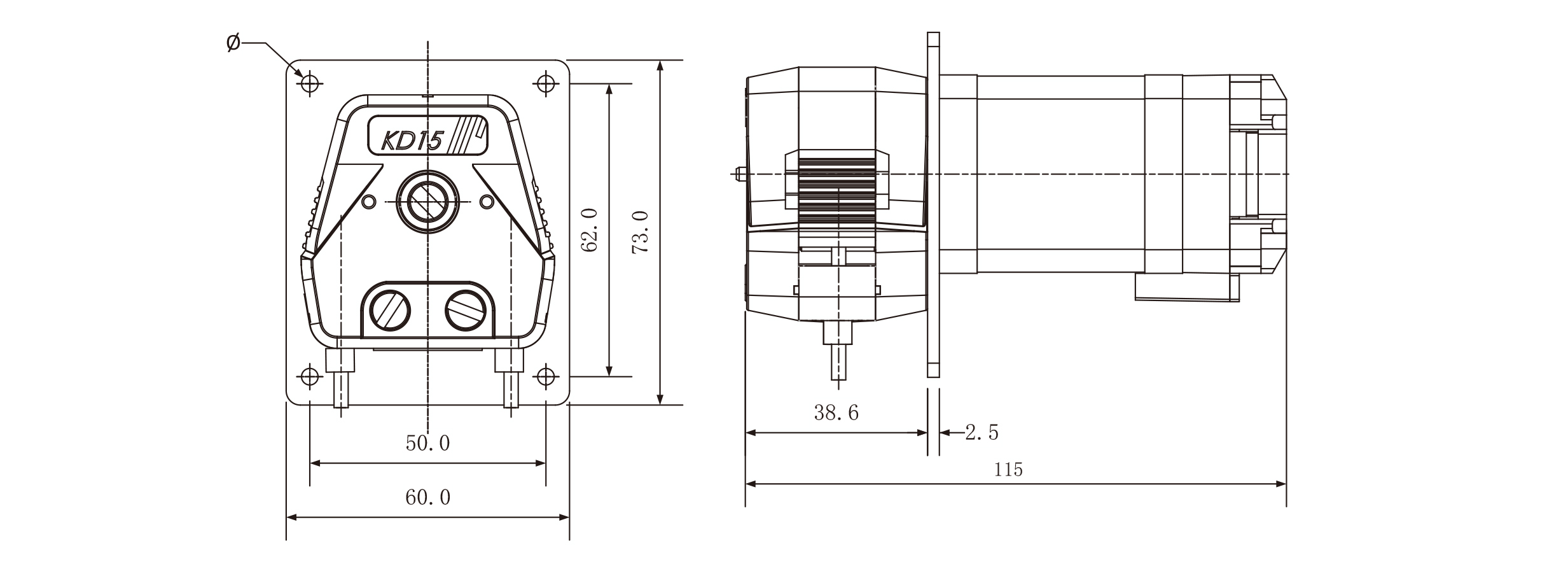
Dimensions(L*W*H): 115*60*73mm
Working Environment:Temperature 0- 40°C, , Relative humidity< 85% RH
Storage Environment: In a clean and well-ventilated environment with ambient temperatures ranging from -40 to +50°C, and relative humidity not exceeding 95%, the air must not contain corrosive, flammable gases, oil mist, or dust.
Tube Model and Flow Reference Table
| Tube Material | Tube No. | Flow Rate(mL/min) | ||||||
| 1rpm | 10rpm | 30rpm | 50rpm8 | 80rpm | 100rpm | 200rpm | ||
| Silicone | 13# | 0.03 | 0.3 | 0.9 | 1.8 | 2.4 | 3.0 | 6.0 |
| 14# | 0.15 | 1.5 | 4.5 | 9.0 | 12 | 15 | 30 | |
| 19# | 0.30 | 3.0 | 9.0 | 18 | 24 | 30 | 60 | |
| 16# | 0.47 | 4.7 | 14 | 28 | 38 | 47 | 94 | |
| 25# | 0.97 | 9.7 | 19 | 58 | 78 | 97 | 194 | |
•The above flow data were all tested using a Lead Fluid silicone tube to pump pure water under laboratory conditions with normal temperature and pressure. This data is for reference only.
•Due to pressure in actual use , temperature, medium characteristics, tube material and other specific factors, the specific situation needs to consult our engineers
Pump Head Structure
Component name and function:
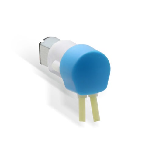
• Pump head pressure block: By pressing the disassembly pressing area on both sides of the pump head pressure block inward and lifting upwards, the pump head pressure block can be disassembled; conversely, by pressing downwards after installing the conduit, the pump head pressure block can be installed.
• Tube slot: The inlet and outlet tubes are fixed in place through the tube slot.
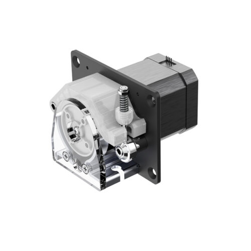
• The stepper motor: The rotation of the stepper motor drives the rotation of the roller.
• The drive control unit: manages the stepper motor’s speed, direction, and operating duration settings.
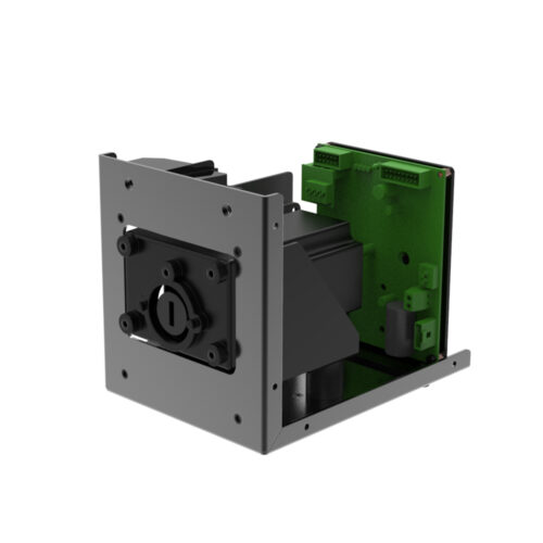
• Mounting plate: It attaches to the customer’s equipment using four through holes on the mounting plate.
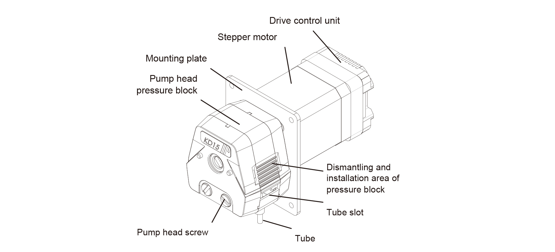
Figure 1 Products Structure
Tube Installation
• Press the regions marked by arrows 1 and 2 in Figure 4 with your hand, then lift in the direction of arrow 3 to detach the pump head pressure block.
• Move Arrows 4 and 5 in the direction opposite to what is indicated, and detach the tube slot;
• Position the center of the hose above the pump’s roller mechanism ( this should be situated below the pump head pressing block before it is removed);
• Insert the two disassembled tube slots into the inner sides of the hose cover/tube connector, and then insert them into the pump head in the direction indicated by the arrows in the figure below.
• Press and hold the pressing areas on the sides of the pump head compression block (indicated by arrow 1 and arrow 2). Push the compression block downward in the direction opposite to arrow 3 until the block is securely placed on the pump head.
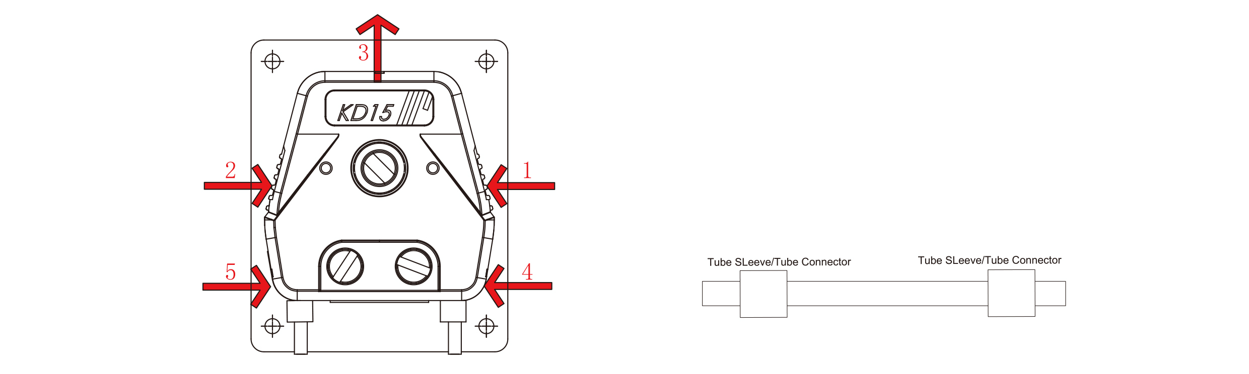
Figure2 Pump Head Installation Diagram Figure3 Pump Head Installation Diagram
Dimension(mm)