Introduction
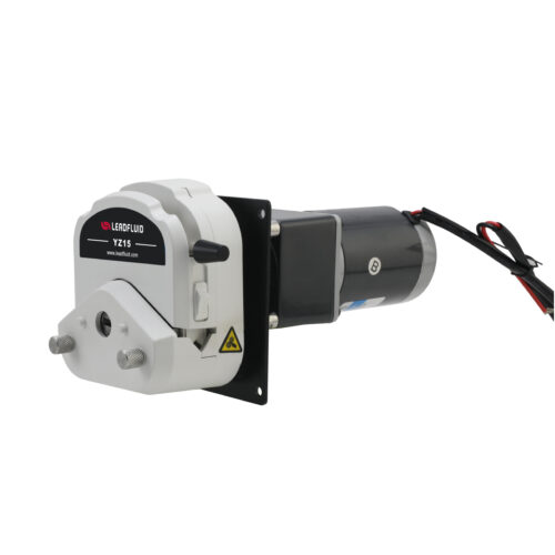
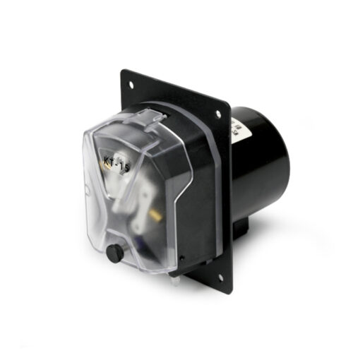
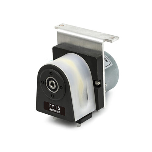
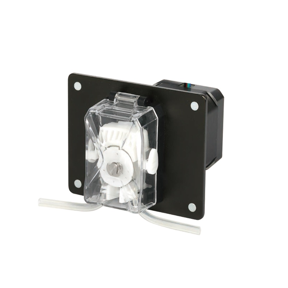
•The WY10 pump head has an exquisite appearance, a compact size, and a tight structure.
•The transparent casing facilitates the observation of the internal operation of the pump head.
•Low operating noise.
•The tube is easy and quick to install, and can adapt to a variety of tube specifications, meeting a wide range of application needs.
•Suitable for a variety of small instruments and equipment, to meet the needs of micro-injection,
rinsing, liquid drainage and other functions.
Parameters
Motor Type: 42 stepper motor
Drive and Control Method: Customer provided
Speed Range: ≤300rpm
Flow Range: ≤73.73ml/min
Cascadeable: Not cascadeable
Channel number: 1
Number of Rollers: 3 rollers
Rotation Direction: Clockwise rotation
Material of Tube: Silicone, Pharmed
Method of Tube Installation: Fixed by pump head
Pressure Tube Type: Pump head tube clamp
Pump Head Shell Material: PC
Pump Head Roller Material: PET
Pump Head Life: ≥3000h
Noise: ≤65dB (test environment noise ≤40dB, test product and noise meter horizontal distance of 1 meter)
Weight: 462.5g (without tube)
Dimensions: (L×W×H) 79.6*63.6*90.6(mm)
Working Environment: Temperature 0- 40°C, relative humidity<80% RH
Storage Environment: Ambient temperature of -20 ~ +50 °C, relative humidity of not more than 95% of the clean and well-ventilated environment, the air shall not contain corrosive, flammable gases, oil mist, dust.
Tube Model and Flow Rate Reference
| Material of Tube | Tube Size (mm) | 10rpm | 50rpm | 100rpm | 300rpm |
| Silicone tube | 1*0.92 | 0.33 | 1.73 | 2.79 | 9.83 |
| 2*0.92 | 1.17 | 5.85 | 11.83 | 35.13 | |
| 3*0.92 | 2.27 | 11.33 | 22.73 | 67.93 | |
| Pharmed | 1.14*0.85 | 0.51 | 2.45 | 5.03 | 15.05 |
| 2.06*0.85 | 1.21 | 6.07 | 12.13 | 36.37 | |
| 3.2*0.85 | 2.46 | 12.37 | 24.57 | 73.73 |
The above data is obtained from the test of purified water with a Lead Fluid tube under normal and pressure conditions in the laboratory. This data is for reference only. Due to pressure in actual use, temperature, medium characteristics, tube material and other specific factors, the specific situation needs to consult our engineers.
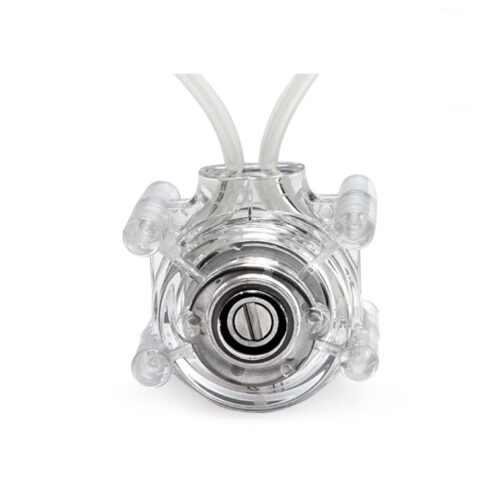
Product Structure & Usage Method
Component Name and Function
1.Guard: Protects the tube and secures the pressure block.
2.Pump Head Spindle: Connects with the driver and motor.
3.Upper Pressure Block: Presses the tube.
4.Left and Right Tube Clamps: Secures the tube.
5.Main Body: Supports the pump head.
6.Roller Body: Supports the roller and connects to the motor spindle.
7.Spring: Drives the tube clamp to secure the tube.
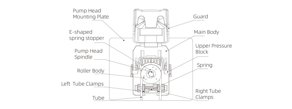
Figure 1 Structure of Pump Head
Usage Method
Tube Installation
Step One: Open the pump head guard, lift the upper pressure block. Clamp the tube with the left and right clamps as shown in Figure 2. The spring will automatically apply pressure, and there is no need to manually squeeze.
Step Two: After clamping the tube with the tube clamps, lower the pressure block to the fixed position until you hear a clicking sound indicating it is in place. Press down on the guard until you hear a clicking sound, as shown in Figure 3. The pump head tube is now installed.
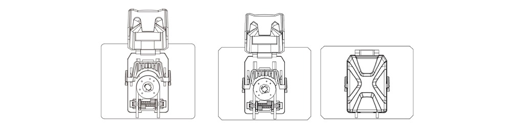
Figure 2 – Pump Head Tube Installation Diagram Figure 3 Pump Head Usage Diagram
Motor Parameters
Phase Number: 2
Step Angle: 1.8°
Rated Voltage: 6.2V
Rated Current/Phase Current: 0.7A(PeakValue)
Phase Resistance: 8.9Ω±10%(20°C)
Phase Inductance: 19.2mH±20%
Electrical Stress: AC500V/1min/5mA Max
Insulation Grade: B (130°C). Temperature rise 80K Max
Ambient Temperature: -10°C-50°C
Lead Wire Specifications: UL1007/AWG26/300±10mm
Dimension Drawing of Exterior and Opening
Unit: mm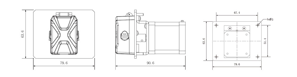 Statement:The final explanation right of above information belongs to Lead Fluid.