Introduction
•The product series includes three models: B150K1DW10-2, B150K2DW10-2, and B150K3DW10-2;
•The control method is analog speed regulation (4-20mA/0-5V/0-10V selectable);
•External level signal control start/stop/direction function;
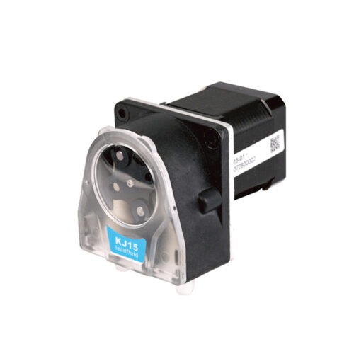
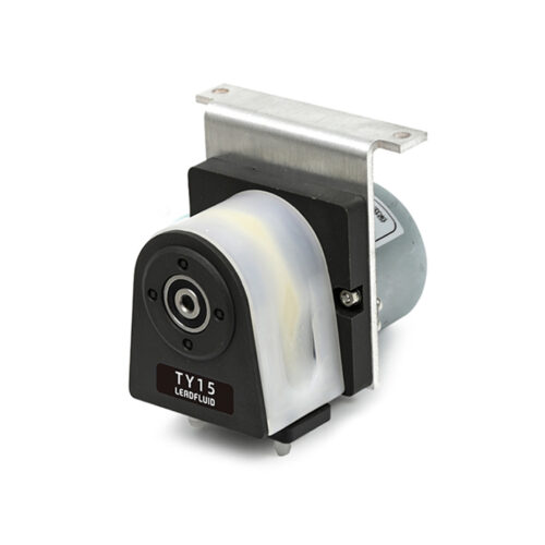
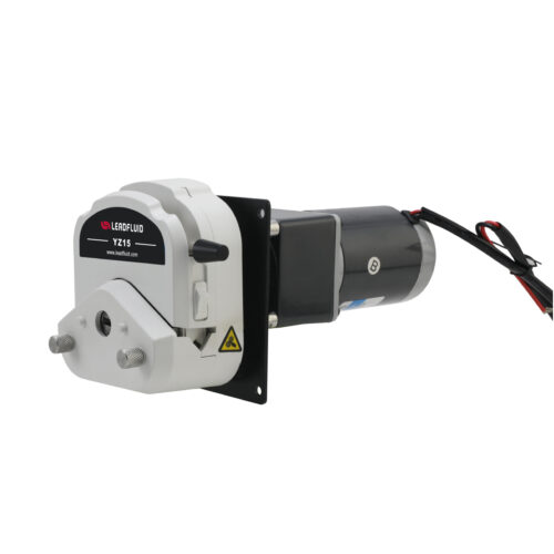
•The product is small in size, compact in structure, and aesthetically pleasing in appearance;
•Selected materials are of high quality, sanitary and non-toxic, with high strength, good toughness, and excellent chemical corrosion resistance;
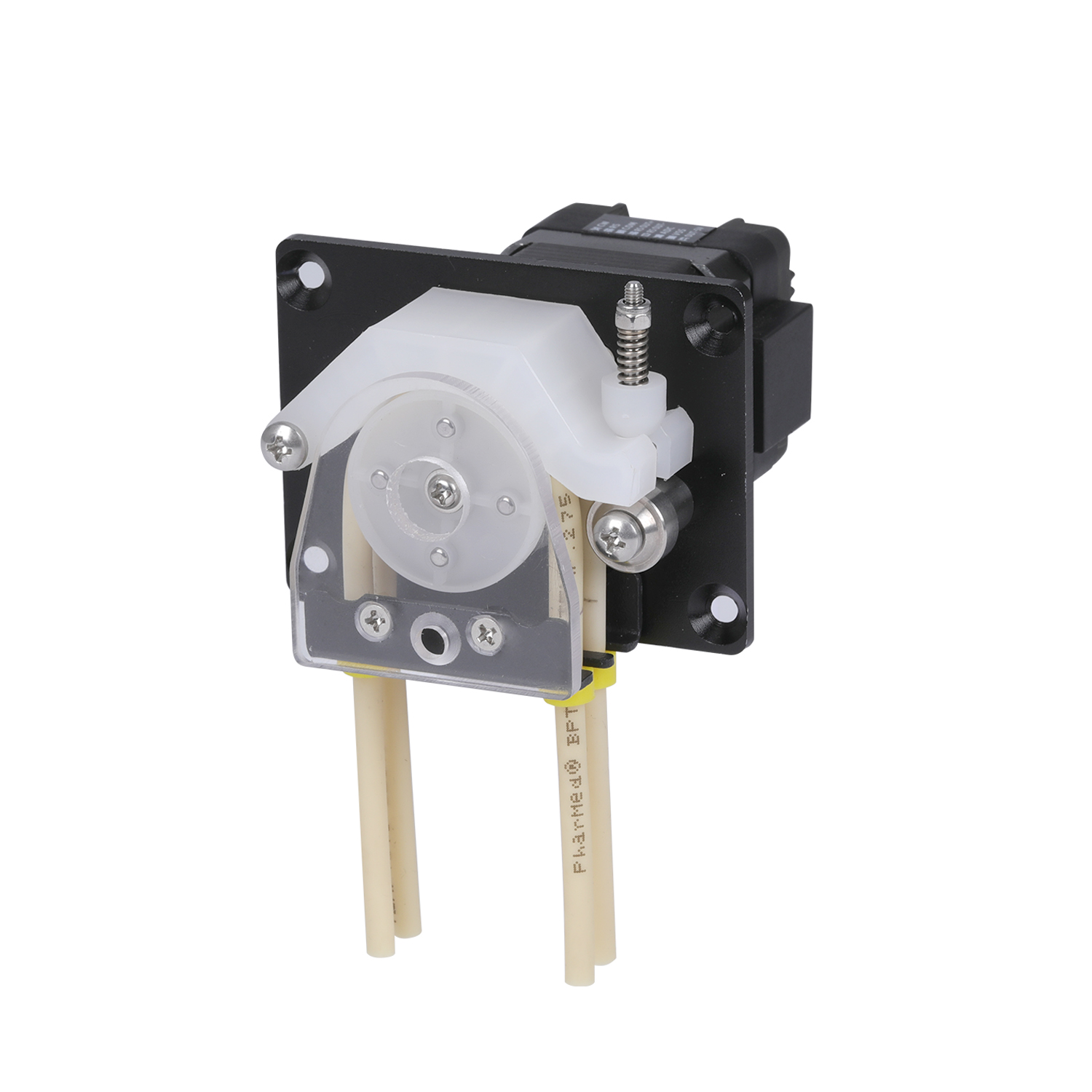
•The pump head uses a spring-pressurized hose fixing structure, which can provide a longer hose life and high-precision flow rate;
•By adjusting the pressure-tube device, the appropriate pressure can be obtained;
•Tube installation is convenient and quick, and it can adapt to various specifications of tubes to meet more application needs;
•This is suitable for low-flow applications and can be used in various instruments and equipment for ODM matching.
Pump Parameters
Motor Types: 42 stepper motor
Power Supply Voltage: DC12-24V
Wattage: <20W
Speed Range: ≤150rpm
Control Mode: Analog signals (4-20mA/0-5V/0-10V)
Start-Stop Method: External Level Signal Control (DC5-24V)
Direction Switch Method: External Level Signal Control (DC5-24V)
Channel Number: 2
Roller Number: 4
Running Direction: Clockwise/Counterclockwise rotation
Adaptable Tube Wall Thickness: 0.85mm
Adaptable Tube ID: 1.52mm/2.06mm
Tube Material: Pharmed
Tube Installation Method: Connector Specifications
Tube-Pressing Type: Spring adjustable
Pump Head Pressure Block Material: PVDF
Material of the Pump Head End Cover: PET
Pump Head Roller Material: PVDF
Pump Head Life: ≥1000h
Noise: ≤60dB (testing environment noise ≤40dB, horizontal distance between test product and noise meter is 1 meter)
Driver Weight: 553g
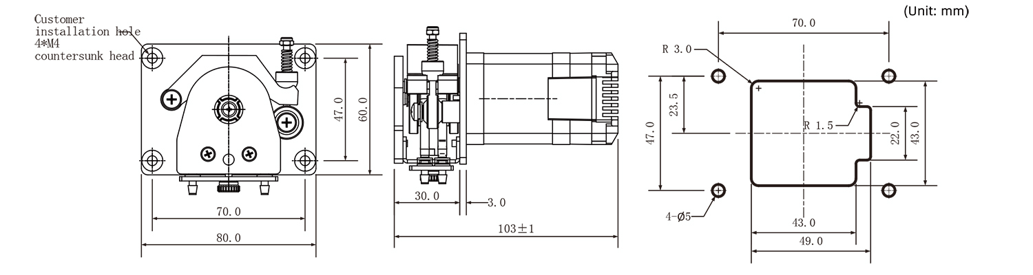
Dimensions: 103*80*60(mm)
Working Environment: Temperature 0- 40°C, , Relative humidity< 85% RH
Storage Environment: In a clean and well-ventilated environment with ambient temperatures ranging from -40 to +50°C, and relative humidity not exceeding 95%, the air must not contain corrosive, flammable gases, oil mist, or dust.
Tube Model and Flow Reference Table
| Tube | Tube No. | Flow Rate(mL/min) | ||||||
| 1rpm | 20rpm | 40rpm | 60rpm | 80rpm | 100rpm (max speed at continuous working) |
150rpm (max running at Intermittent working) |
||
| Pharmed | 1.52*0.85 | 0.1 | 2 | 4 | 6 | 8 | 10 | 15 |
| 2.06*0.85 | 0.15 | 3 | 6 | 9 | 12 | 15 | 22.5 | |
•It is recommended to operate intermittently for speeds above 100rpm. An example of an intermittent operation mode is: run for 3 seconds, stop for 2 seconds,
and repeat the cycle.
•The above flow data were all tested using a Lead Fluid silicone tube to pump pure water under laboratory conditions with normal temperature and
pressure. This data is for reference only.
•Due to pressure in actual use , temperature, medium characteristics, tube material and other specific factors, the specific situation needs to consult
our engineers.
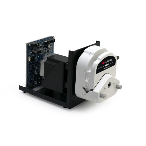
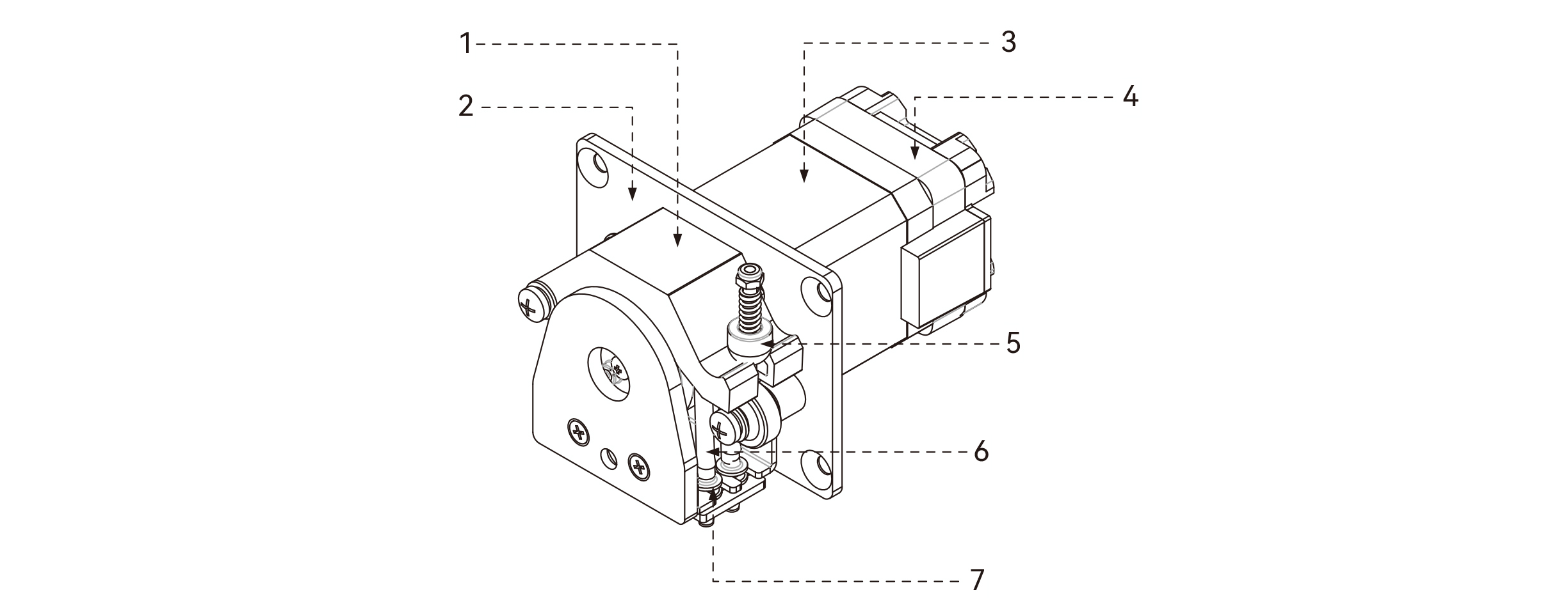
Product Structure
Component name and function:
1.Pump head pressure block: Squeezing the tube with rollers.
2.Mounting Plate: Connects the motor to the pump head bracket and can also be used to install the product onto other equipment;
3.Motor: Drives the pump head;
4.Drive and Control Unit: Provides power, sets operating modes;
5.Commutation screw: Matched with the pump head pressure block;
6.Tube: Transmission of liquid;
7.Tube connector: Securing and connecting tubes.
Usage Method
Tube Disassembly
• Step 1: Turn the hand screw counterclockwise to unscrew it, then remove the pressure plate.
• Step 2: First, turn the directional screw down, then lift the pressure block upwards and remove the tube-line and the tube connectors.
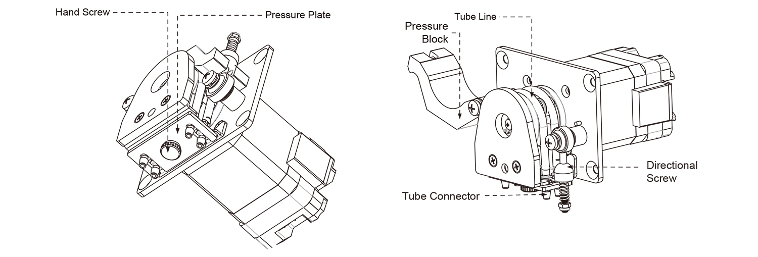
Tube Installation
The installation method is the opposite of the disassembly steps mentioned above.
Dimension(mm)