Features
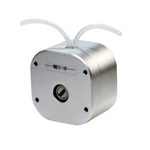
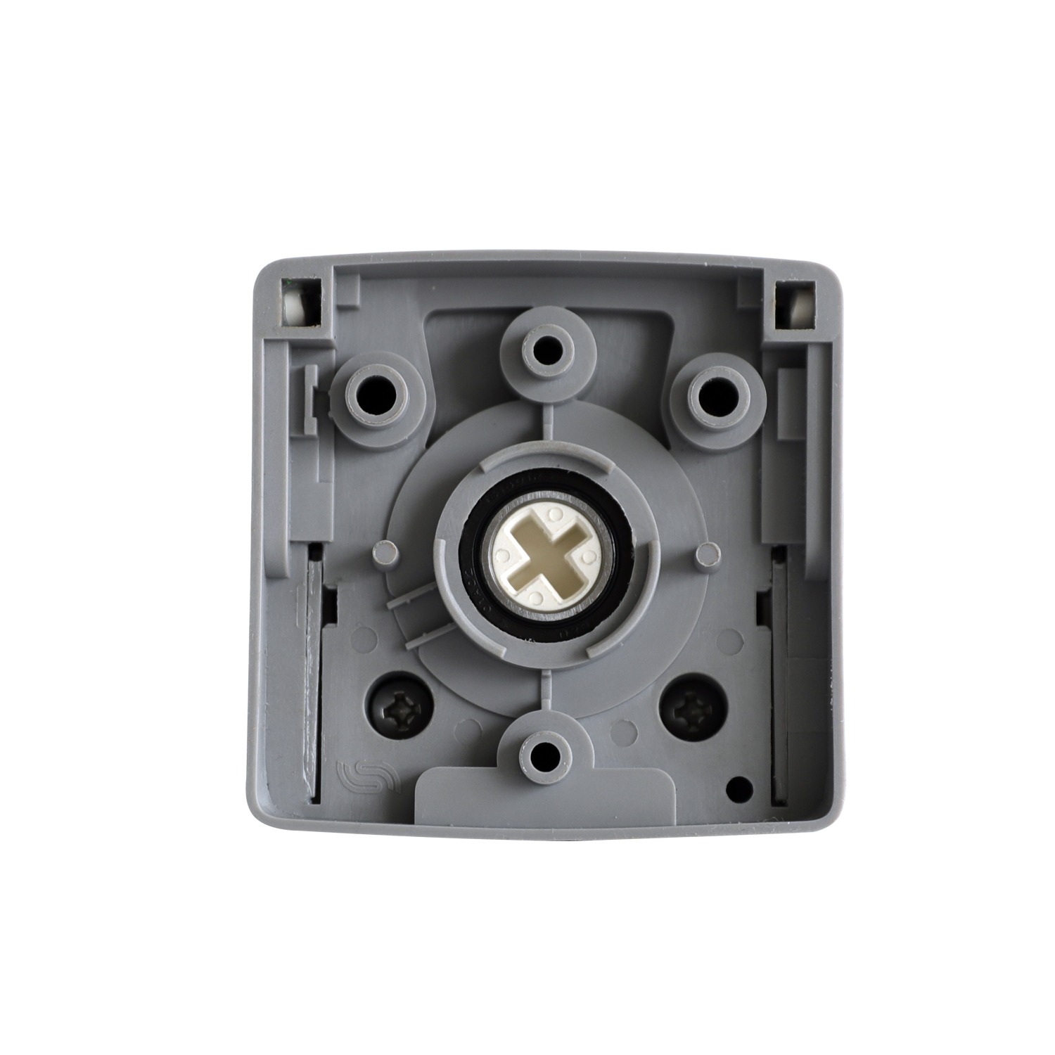
• Compact and Exquisite, Ideal for OEM Integration
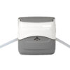
The pump head boasts an elegant appearance and compact structure, making it easy to integrate into various instruments and devices, effectively saving space.
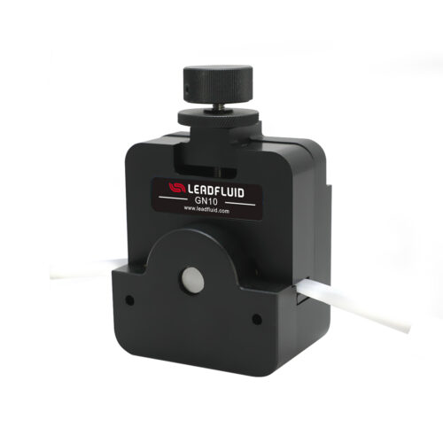
• Single-Handed Operation for Enhanced Efficiency
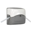
The flip-top design allows for quick one-handed tube installation. Tubes automatically position and lock without adjustment, significantly improving work efficiency
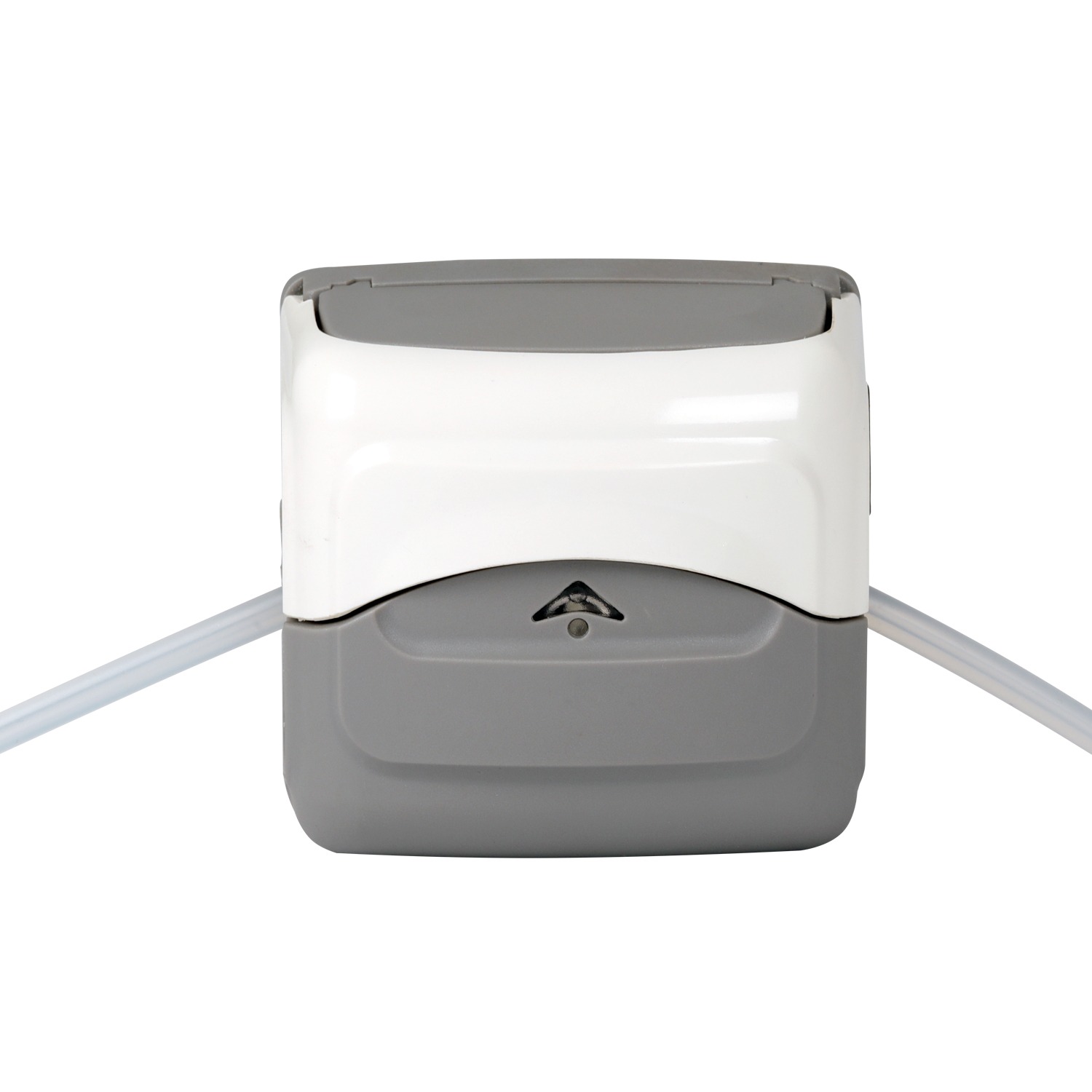
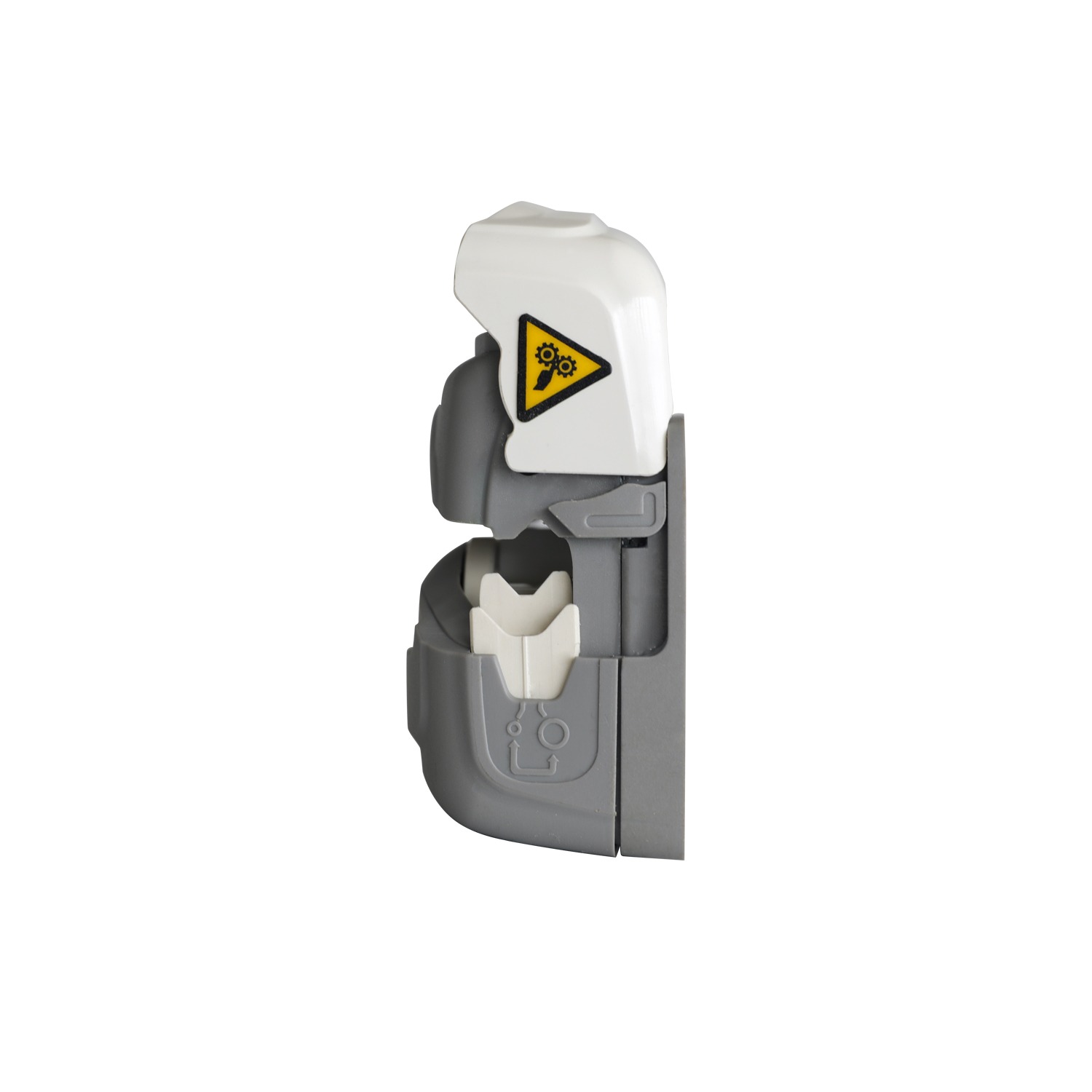
• Observation window and cover indicator for clear user experience
The observation window also serves as a cover opening indicator. The internal operation status is clearly visible, and the cover opening guide is straightforward, significantly enhancing the user experience.
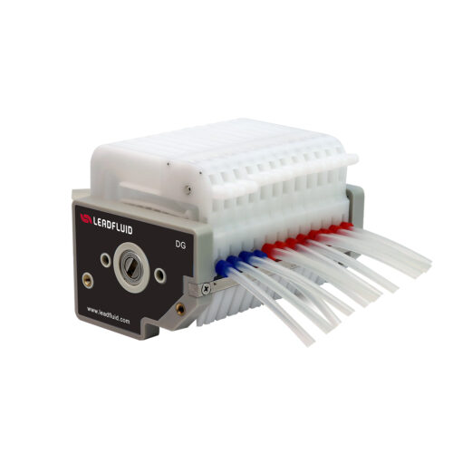
• Spring Block Design to Extend Tubing Life
The spring block design extends the life of the tube, ensures stable flow output, reduces pulsation, and guarantees high-precision fluid control.
•Low Pulsation
The four-roller design provides precise and consistent low-pulsation flow control.
•High Flow Rate
The maximum continuous flow rate is 370 mL/min, and the maximum intermittent flow rate is 550 mL/min.
•Flexible Compatibility with Various Tube Sizes
Supports six tube sizes with a wall thickness of 1.6mm, accommodating diverse application scenarios.
•Two Models: Standard and High Pressure
The adjustable spring offers standard and high-pressure models to meet different usage needs.
•Optional Cover Opening Stop and Speed Monitoring Features
Optional features include cover opening stop and speed monitoring, ensuring safe operation and monitoring the running status.
Pump Head Specifications
Channel: 1
Roller: 4
Tubing fixing: Spring tube clamp, divided into two adjustable levels: large tube clamp and small tube clamp
Applicable tube material: Silicone,Pharmed,A-60-G,PVC,Viton
Clearance adjustment: Adjustable
Material: Reinforced nylon, PET
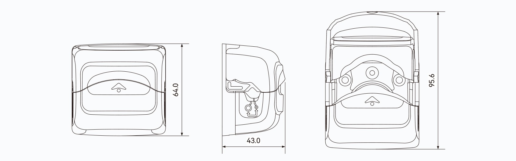
Dimension: 64×64×43mm
Working environment: Temperature 0 ~ 40℃, relative humidity<80%
Optional function: Cover opening stop,speed monitoring
Weight: 102g
Flow Parameters
Test tube wall thickness 1.6mm
| Tube Material | Max Speed(rpm) | Applicable Tube | Max Flow Rate(mL/min) |
| Silicone | 400(continuous) | 120#,13#,14#,19#,16#,25# | 370 |
| 600(intermittent) | 550 |
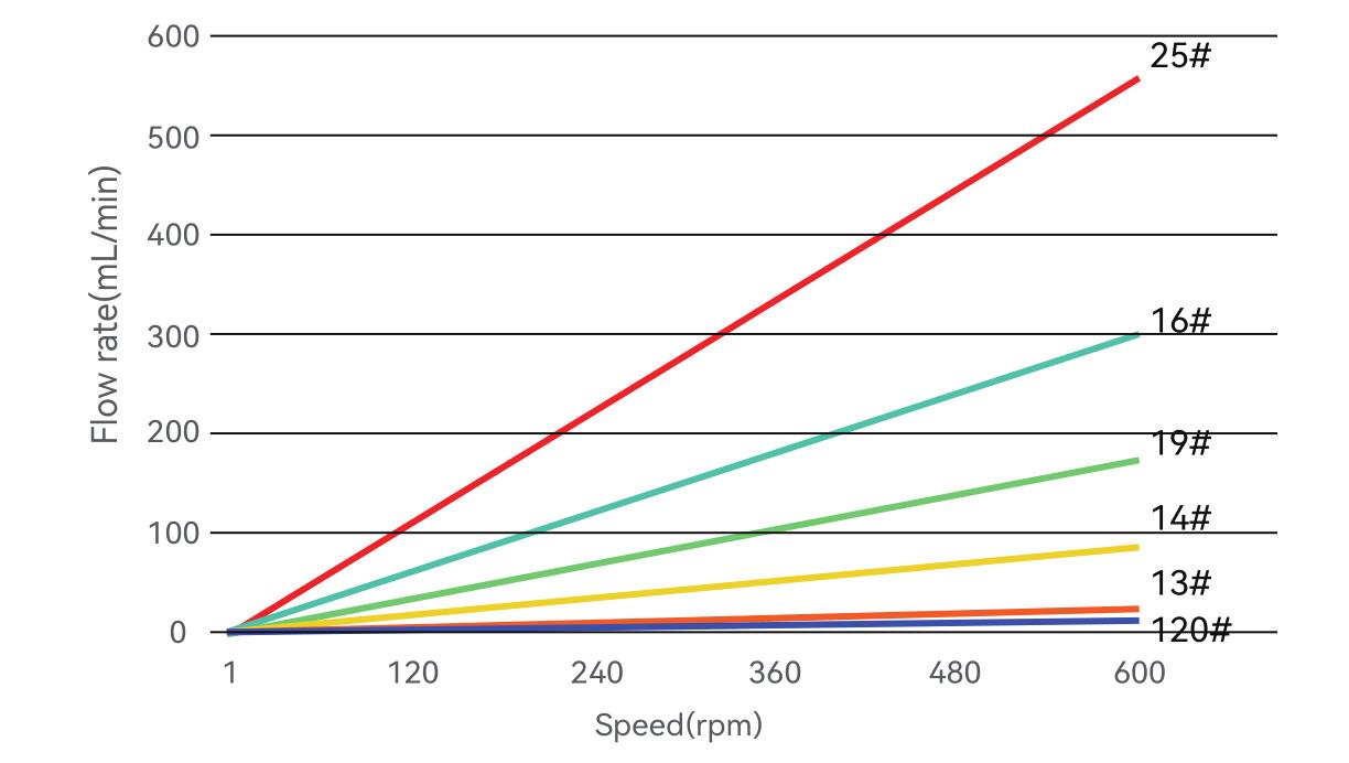
FT1505 Applicable Tube and Flow
Unit:mL/min
| Tube model | 1rpm | 30rpm | 60rpm | 100rpm | 200rpm | 400rpm | 600rpm(intermittent) |
| 120# | 0.02 | 0.6 | 1.2 | 2.1 | 4.3 | 8.7 | 12.9 |
| 13# | 0.04 | 1.2 | 2.5 | 4.1 | 8.3 | 16.5 | 25 |
| 14# | 0.14 | 4.2 | 8.5 | 14 | 28 | 57 | 85 |
| 19# | 0.29 | 8.7 | 17.5 | 29 | 58 | 115 | 175 |
| 16# | 0.5 | 15 | 30 | 50 | 100 | 200 | 300 |
| 25# | 0.92 | 27 | 55 | 92 | 184 | 370 | 550 |
Note: The inlet and outlet tubes are each 500 mm long and lie on the same horizontal plane. Variations in the operating conditions, including the type of liquid,
viscosity, tube length, and pressure difference between the inlet and outlet, will affect the flow rate. For further assistance, please consult our engineer.
The standard pump flow chart is provided for reference. For non-standard or special flow requirements, we offer professional customization services to precisely match
your application scenarios.
Tube Clamp Selection
| Tube Clamp Selection | Tube Specifications | |||||
| 120# | 13# | 14# | 19# | 16# | 25# | |
| Small clamp | √ | √ | √ | √ | √ | x |
| Large clamp | x | x | x | √ | √ | √ |
Adjustable tube clamp to better accommodate tube with ID from 0.5mm to 4.8mm.
FT1505 Pump Head Speed and Flow Curve
Method for Switching Pump Head Clamp
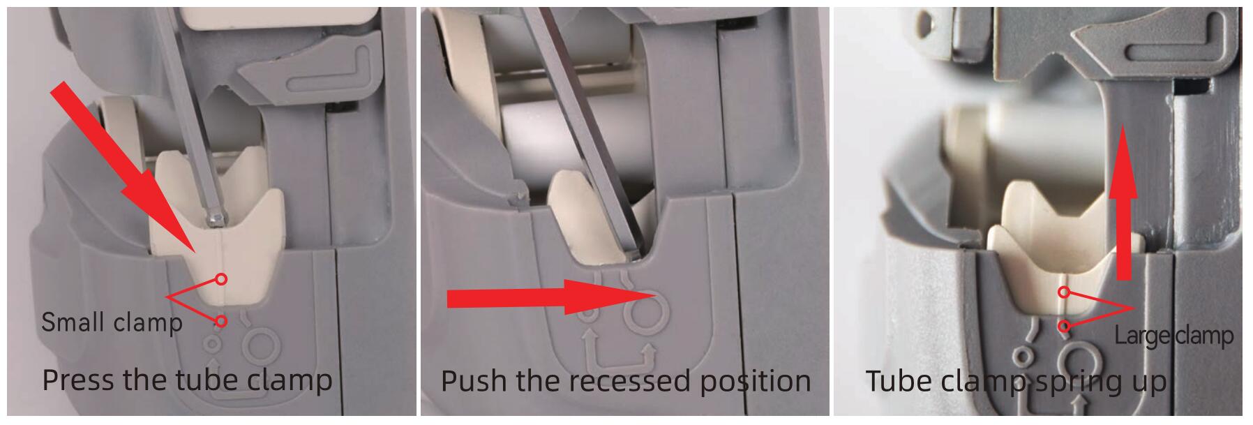
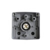
• Press the tube clamp obliquely downwards towards the target switching position until the upper part of the tube clamp is disengaged from the limit point.
• Continue to push the recessed position obliquely downwards into the target position of the tube clamp switch; the tube clamp will spring up, completing the switch, as shown in the figure below.
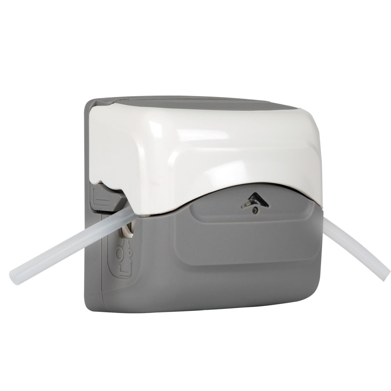
Tubes Installation Process Diagram
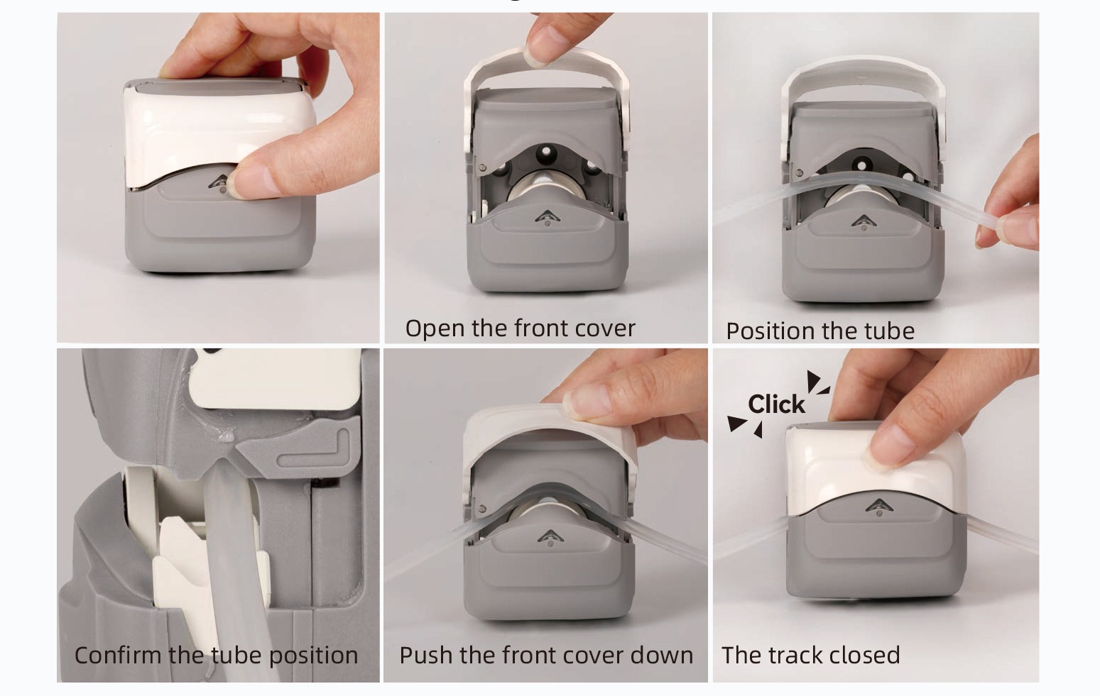
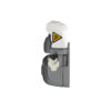
Open the front cover until fully opened
• A space for installing the tube is created between the movable front casing and the pump head core, where the tube is then positioned.
• Make sure the internal soft tube in the pump head is properly aligned so it can extend naturally without any twists or turns.
• Push the movable front cover down until it clicks. Once you hear the click, the front cover locks into place, the track automatically closes, and the tube is automatically stretched and secured in this process.
Dimensions(mm)
Ordering Information
| Product Model | Description | Pressure Range(Mpa) | Order Number |
| FT1505 | Standard Pressure Pump Head | 01-0.15 | 1090200101014 |
| FT1505-H | High Pressure Pump Head | 0.15-0.25 | 1090200101015 |