Introduction
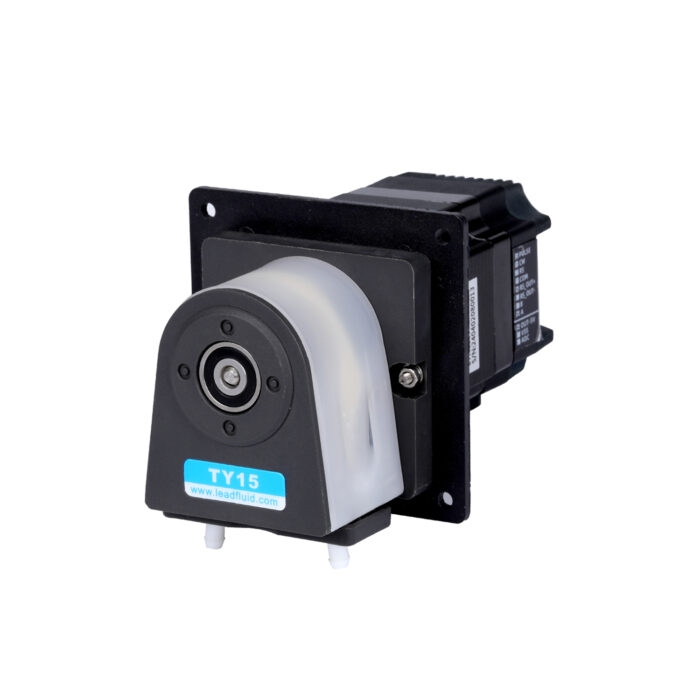
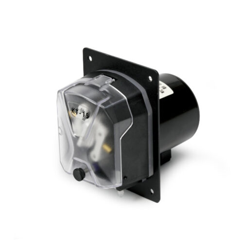
•This product series includes three models: B200K1TY15, B200K2TY15, and B200K3TY15;
•External analog quantity to adjust the speed, analog quantity 0-5V/0-10V/4-20mA.
•External signal controls start and stop, forward and reverse rotating, external control signal 12-24V wide range input, optoelectronic isolation.
•TY15 spring easy-install pump head adopts a quick-installation structure design, flexible upper pressure block, spring roller structure, and convenient and quick tube installation;
•Small and compact with an attractive and aesthetically pleasing design
•Long service life of tubes;
•Quiet operation;
•Good mechanical strength and resistance to pollution;
•Suitable for small and medium flows;
•Suitable for COD and CEMS online monitoring usage;
•To facilitate use in ODM support, it is designed to be compatible with various devices, instruments, and laboratory settings.
Application Fields: Biopharmaceuticals, Industrial, Food Industry, and More
Typical Applications: Biocatalyst Transfer, Drug Filtration, Drug Transfer, etc.
Parameters
Motor types: 57 stepper motor
Power supply voltage: DC 24-36V
Control mode: External analog
External control functions: The speed adjustment range for analog inputs of 0~5V/0~10V/4~20mA is 0-200 rpm. The external level signal determines both the motor’s start/stop function and its direction.
Speed range: ≤200rpm
Flow rang: ≤280mL/min
Channel number: 1 Channel
Roller number: 2 rollers
Running direction: Clockwise/counterclockwise rotation
Tube material: Silicone tube, Pharmed, A-60-G
Tube installation method: Tube connector
Type of tube pressure: Fixed gap
Pump head shell material: IXEF
Material of pump head roller: PET+PPS
Material of pump head pressure block: PVDF
Material of the roller shaft: S304 Stainless Steel
Life span: ≥1000h
Noise: ≤ 60db (testing environment noise ≤40dB, horizontal distance between test product and noise meter is 1 meter)
Driver weight: 0.417Kg (Without tube)
Dimensions (L*W*H): 137mm*82mm*82mm
Wattage: ≤30W
Working environment: Temperature 0- 40°C, , Relative humidity< 85% RH
Storage environment: In a clean and well-ventilated environment with ambient temperatures ranging from -40 to +50°C,and relative humidity not exceeding 95%, the air must not contain corrosive, flammable gases, oil mist, or dust.
Tube Model and Flow Reference Table
| Model | Tube Material | Tubes No. | mL/rpm | 10pm | 100pm | 200pm |
| B200K1TY15 B200K2TY15 B200K3TY15 |
Silicone | 13# | 0.05 | 0.5 | 5 | 10 |
| 14# | 0.17 | 1.7 | 17 | 34 | ||
| 19# | 0.4 | 4 | 40 | 80 | ||
| 16# | 0.75 | 7.5 | 74 | 148 | ||
| 25# | 1.4 | 14 | 140 | 280 |
• The above flow data were all tested using a Lead Fluid silicone tube to pump pure water under laboratory conditions with normal temperature and pressure. This data is for reference only.
• Due to pressure in actual use , temperature, medium characteristics, tube material and other specific factors, the specific situation needs to consult our engineers.
Head Pump Structure
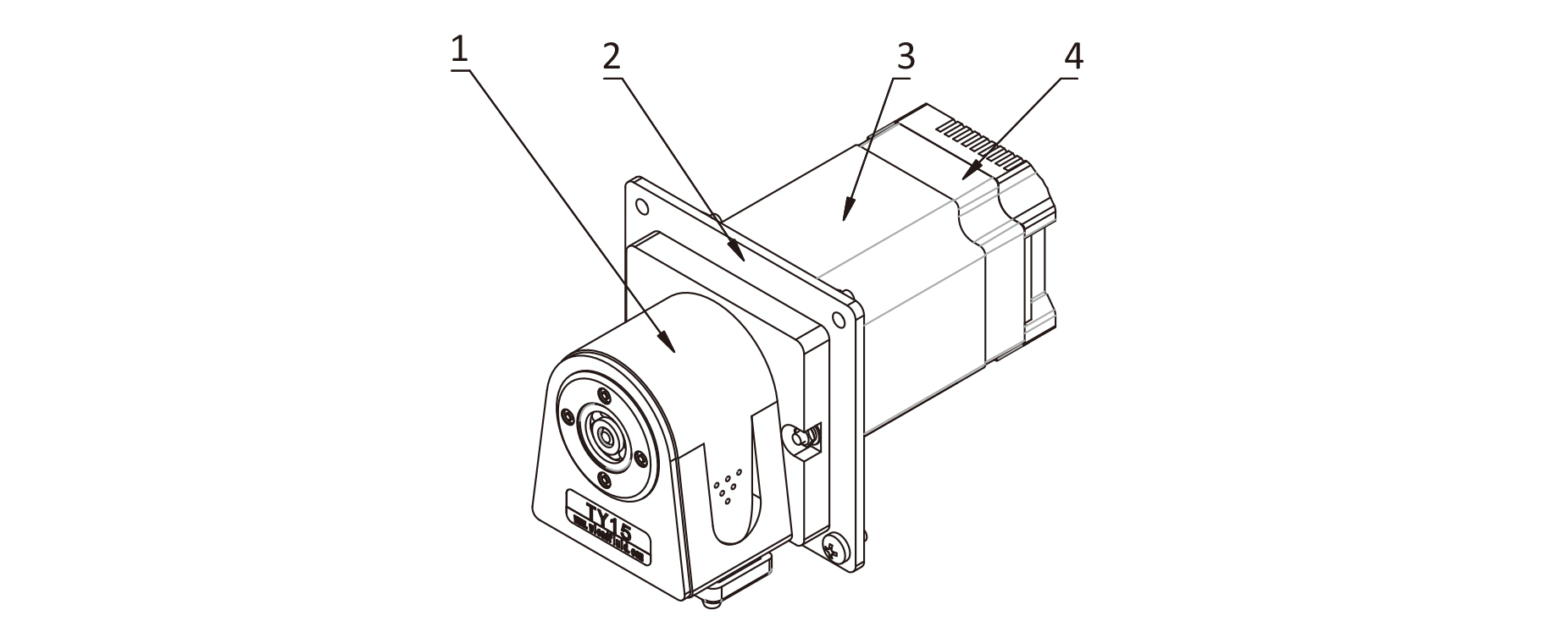
Component name and function:
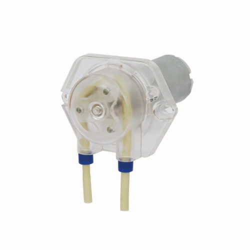
1. TY Pump Head: Attach a tube for liquid transfer;
2. Mounting Plate: This component connects the motor to the pump head and also allows the product to be mounted onto other equipment;
3. Motor: Provides power;
4. Drive Unit: Controls the motor speed and start/stop functions using external analog signals.
Figure 1 Products Structure
Usage Method
Disassemble the TY15 pump head
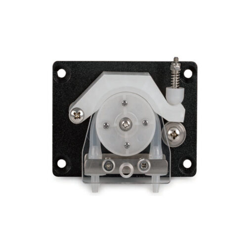
Step 1: Push the upper pressure plate lock using the direction indicated by the arrow on your finger, then open the upper pressure plate.
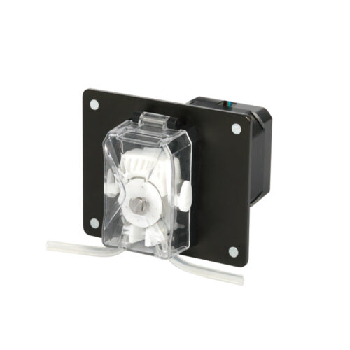
Step 2: Hold the latches on both sides and move them upward to open the unit, then remove part number 1, the “upper pressure block,”as shown in Figure 3.
Step 3: Detach the tube joint as illustrated in Figure 4.
Install the TY15 pump head
Reverse the disassembly sequence
Figure2 Diagram of Pump Head Disassembly(1) Figure3 Diagram of Pump Head Disassembly(2) Figure4 Diagram of Tube-line Disassembly
