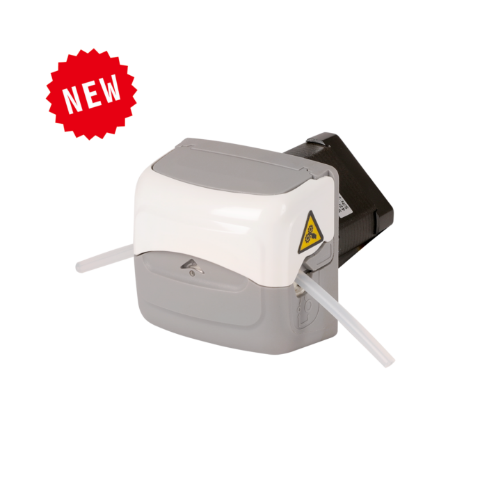
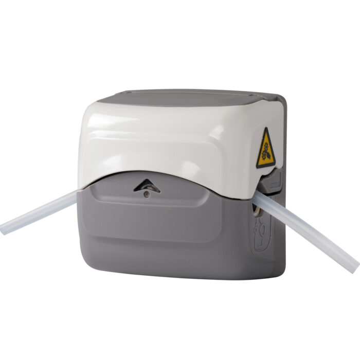
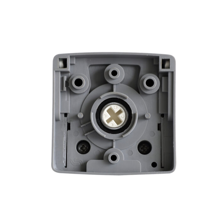
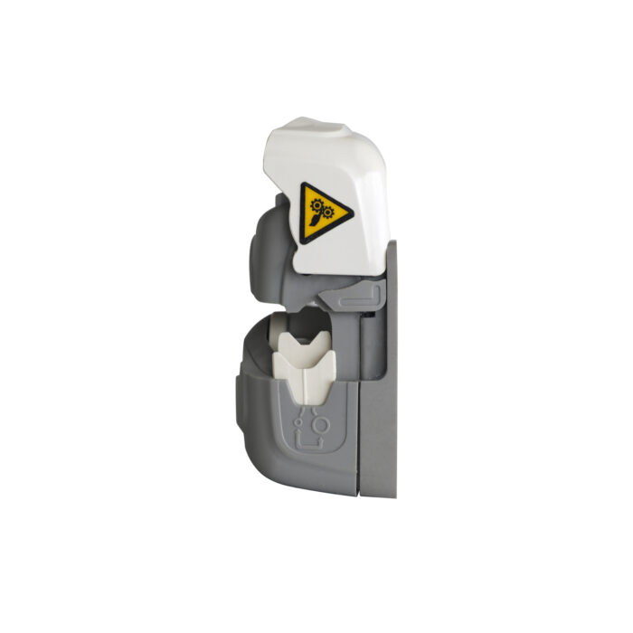
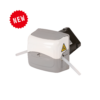
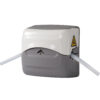
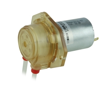
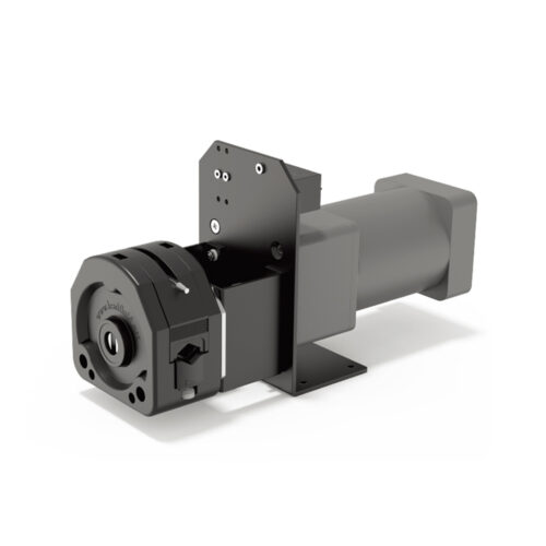
Peristaltic Pump Introduction
•Combines performance, operation, and practicality;
•The product is designed with a compact structure and small size, offering a larger flow rate compared to other products of the same dimensions.
•Using a flip-cover structure, it provides the maximum tubing space within limited dimensions;
•Convenient tube installation, automatic positioning and tensioning of the tube after installation, no repeated adjustments required;
•Spring pressure block design, maintaining good pressure performance and good tube suitability;
•The device features an observation window, enabling a clear view of the pump head in operation;
•The main body is constructed from reinforced nylon, ensuring strength and durability;
•Pulse stability;
•The stepper motor drive eliminates the need for special maintenance of the pump head.
Application
•Compact in size, making it particularly suitable for locations with limited space;
•Precise measurement and transmission of flow, with an emphasis on small flow rates;
•Easy to integrate in OEM setups.
Function and Features
• The drive motor is directly connected to the pump head, making installation and use very convenient.
• The outer shell is made from reinforced nylon, while the roller is crafted from PET material.
• With high corrosion resistance, the performance is reliable.
• Flip cover design, easy to use and quick, saves operating space,
• Replacing the tube is easy and straightforward, and the versatile tube clamp can adapt to different tube sizes.
• The clamp’s position can be adjusted and switched to fit various tube specifications, ensuring it meets different installation needs.
Pump Parameters
| Motor Types | 42 stepper motor |
| Control and Drive Methods | User-supplied |
| Speed Range | Continuous operation ≤400rpm; Intermittent operation ≤600rpm |
| Maximum Flow Rate in Continuous Operation | 370mL/min (silicone tube) |
| Maximum Flow Rate in Intermittent Operation | 550mL/min (silicone tube) |
| Channel number | 1 channel |
| Roller number | 4 rollers |
| Running Direction | Clockwise/Counterclockwise rotation |
| Suitable Tube Wall Thickness | 1.6 mm |
| Suitable Tube Specifications | 120#, 13#, 14#, 19#, 16#, 25# |
| Tube Material | Silicone tube, Pharmed |
| Tube installation method | Adaptive tube clamps |
| Types of Tube Pressure | Elastic Gap |
| Material of the pump head shell | Enhancing Nylon |
| Material of Pump Head Roller | Roller: PET; Metal parts: 304; |
| Noise | ≤ 60db (testing environment noise ≤40dB, horizontal distance between test product and noise meter is 1 meter) |
| Pump Head Weight | 470g (without tube) |
| Dimensions | 64mm×64mm×91mm |
| Working environment | Temperature 0- 40°C, , Relative humidity< 85% RH |
| Storage Environment | In a clean and well-ventilated environment with ambient temperatures ranging from -40 to +50°C, and relative humidity not exceeding 95%, the air must not contain corrosive, flammable gases, oil mist, or dust |
Tube Model and Flow Reference Table
| Tube | Speed | mL/rpm | 30rpm | 60rpm | 100rpm | 200rpm | 400rpm | 600rpm |
| 30rpm | 120# | 0.02 | 0.6 | 1.2 | 2.1 | 4.3 | 8.7 | 12.9 |
| 13# | 0.04 | 1.2 | 2.5 | 4.1 | 8.3 | 16.5 | 25 | |
| 14# | 0.14 | 4.2 | 8.5 | 14 | 28 | 57 | 85 | |
| 19# | 0.29 | 8.7 | 17.5 | 29 | 58 | 115 | 175 | |
| 16# | 0.5 | 15 | 30 | 50 | 100 | 220 | 300 | |
| 25# | 0.92 | 27 | 55 | 92 | 184 | 370 | 550 |
Note: 600rpm is intermittent operation.
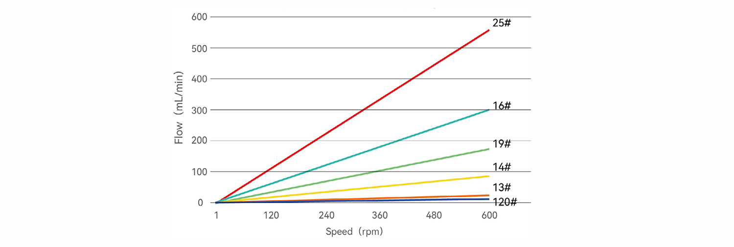
Speed-Flow Relationship Diagram
• The above flow data were all tested using a Lead Fluid silicone tube to pump pure water under laboratory conditions with normal temperature and pressure. This data is for reference only.
• Due to pressure in actual use , temperature, medium characteristics, tube material and other specific factors, the specific situation needs to consult our engineers.
Head Pump Structure
Component name and function:
1.Active Front Cover: Flipping open or closing the active front cover allows access to the pump head tube compartment;
2.Observation window: For viewing the rotation state of the pump head;
3.The main body: used for motor installation and providing overall machine installation positions;
4.Support: used to support the pump head core;
5.Pump head core: As the working part of the squeeze tube;
6.Position of Tube Clamp: Indicates the current position of the tube clamp;
7.Motors: Provide power.
Figure 1 Products Structure
Figure 2 Pump Head Installation Diagram
Usage Method
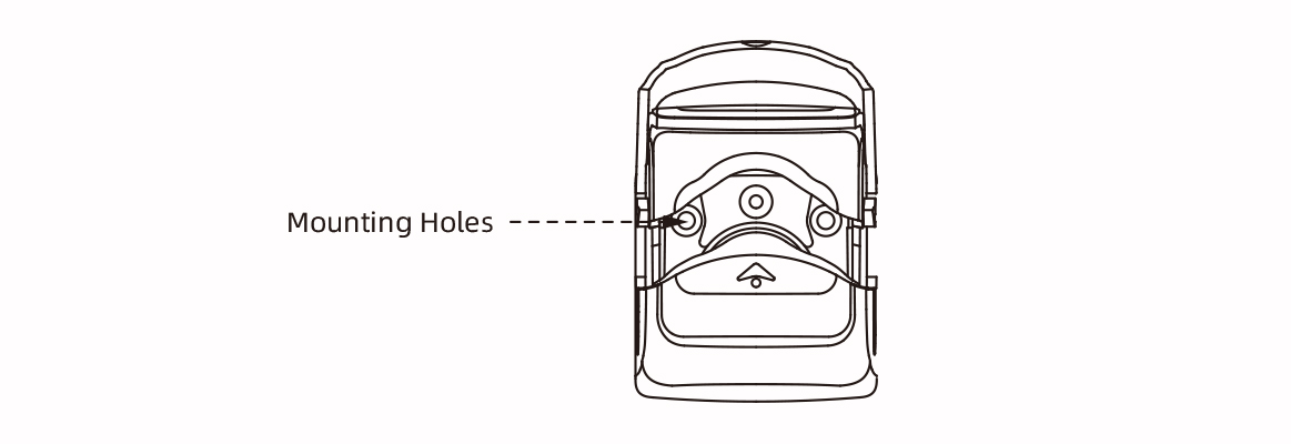
tep 1: According to the direction shown in the figure, embed the motor into the device,and use 2 M4 pan head screws or hexagon socket screws to fix the pump head onto the device at the mounting hole position.
Usage Method
Step 2: Open the front cover of the activity until it is fully open;
Step 3: Form a tube installation space between the active front cover and the pump head core, and place the tube in this space; straighten the tube inside the pump head, ensuring that it is naturally extended, without twisting or misalignment.
Step 4: Snap the moveable front shell downward until you hear a click. This indicates that the front shell is locked in place, the track has automatically closed, and the tube has been stretched and secured during this.
Figure 3 Tubes Installation Process Diagram
Dimension(mm)
