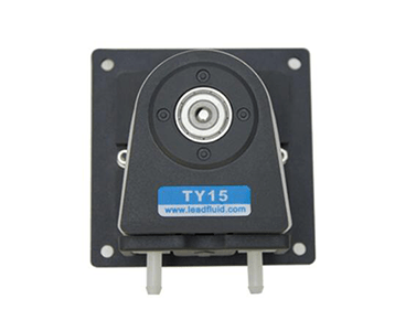
Introduction
•With forward and reverse rotating, start and stop, speed regulation and full speed functions.
•High precision speed control.
•RS485 communication, support MODBUS protocol, a variety of communication parameters can be set, easy to connect with various control equipment.
•Small and compact with an attractive and aesthetically pleasing design
• Quiet operation;
•The pump head shell is made of transparent polycarbonate (PC), allowing the internal operation to be observed during functioning;
•The roller is made from S304 stainless steel, known for its corrosion resistance;
• Ideal for continuous operation at high speeds;
• General installation size, can be used in cascade;
• Perfect for small to medium flow applications, this equipment can be seamlessly integrated with devices, instruments, and laboratory setups.
Pump Parameters
Motor Types: 57 stepper motor
Power Supply Voltage: DC 24-36V
Control Mode: RS485 Communication
Communication Mode: RTU
Communication Address: 1- 16
Communication Rate: 9600
Data Bit: 8
Check Bit: Parity check/No parity check
Stop Bit: 1
Speed Range: ≤350rpm
Flow Rang: ≤910mL/min
Channel Number: 1 Channel
Roller Number: 3 Rollers
Running Direction: Clockwise/Counterclockwise rotation
Tube Material: Silicone Tube, Pharmed, A-60-G
Tube Installation Method: Built-in tube
Tube Pressure Types: Fixed gap
Pump Head Shell Material: PC
Roller Material: S304 stainless steel
Life: ≥4000h
Noise: ≤ 60db (testing environment noise ≤40dB, horizontal distance between test product and noise meter is 1 meter)
Driver Weight: 1.683kg (Without Tube)
Dimensions (L*W*H): 213*116*74(mm)
Wattage: ≤30W
Working Environment: Temperature 0- 40°C, , Relative humidity< 85% RH
Storage Environment: In a clean and well-ventilated environment with ambient temperatures ranging from -40 to +50°C, and relative humidity not exceeding 95%, the air must not contain corrosive, flammable gases, oil mist, or dust.
Tube Model and Flow Reference Table
| Model | Tube Material | Tube No. | Flow Rate (mL/min) | |||
| 1pm | 10pm | 100pm | 350pm | |||
| B350K5BZ25-24 | Silicone | 24# | 2.6 | 26 | 260 | 910 |
•The above flow data were all tested using a Lead Fluid silicone tube to pump pure water under laboratory conditions with normal temperature and pressure. This data is for reference only.
•Due to pressure in actual use , temperature, medium characteristics, tube material and other specific factors, the specific situation needs to consult our engineers.
Head Pump Structure
Component name and function:
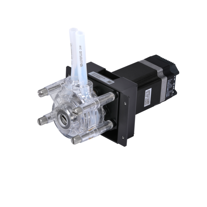
1. Pump head: Install tube-lines to transport liquid.
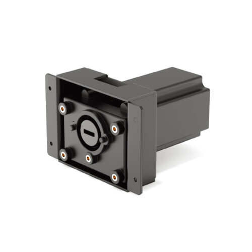
2. Mounting Plate: Connects the motor and pump head bracket, and can also be used to install the product onto other equipment.
3. Motors: Providing power
4. Control and Drive Unit: RS485 communication control.
Note: A pump tube pressure lever, a 200mm silicone tube, and four single-channel installation screws are included with the product.

Figure 1 Diagram of Pump Structure Figure 2 Pump Head Structure Diagram Figure 3 Tube Pressure Lever
Usage Method
Tube Installation
• Open the pump head shell and use a tube pressure lever to secure the tube at the illustrated position.
• Turn the tube lever counterclockwise and insert the tube between the roller and the pump shell.
• After fastening the other pump shell, use a tube lever to rotate the main shaft following the instructions in the diagram, and adjust the tube
position inside the shell.

Figure 4 Tube Installation Diagram (1) Figure 5 Tube Installation Diagram (2) Figure 6 Tube Installation Diagram (3)
Pump Head Installation
Insert the extended end (flat shaft part) of the pump head’s main shaft into the coupling groove, and then secure it with screws.
